
1. Introduction to Antennas
An antenna is a transition structure between free space and a transmission line, as shown in Figure 1. The transmission line can be in the form of a coaxial line or a hollow tube (waveguide), which is used to transmit electromagnetic energy from a source to an antenna, or from an antenna to a receiver. The former is a transmitting antenna, and the latter is a receiving antenna.

Figure 1 Electromagnetic energy transmission path
The transmission of the antenna system in the transmission mode of Figure 1 is represented by the Thevenin equivalent as shown in Figure 2, where the source is represented by an ideal signal generator, the transmission line is represented by a line with characteristic impedance Zc, and the antenna is represented by a load ZA [ZA = (RL + Rr) + jXA]. The load resistance RL represents the conduction and dielectric losses associated with the antenna structure, while Rr represents the radiation resistance of the antenna, and the reactance XA is used to represent the imaginary part of the impedance associated with the antenna radiation. Under ideal conditions, all the energy generated by the signal source should be transferred to the radiation resistance Rr, which is used to represent the radiation capability of the antenna. However, in practical applications, there are conductor-dielectric losses due to the characteristics of the transmission line and the antenna, as well as losses caused by reflection (mismatch) between the transmission line and the antenna. Considering the internal impedance of the source and ignoring the transmission line and reflection (mismatch) losses, the maximum power is provided to the antenna under conjugate matching.

Figure 2
Because of the mismatch between the transmission line and the antenna, the reflected wave from the interface is superimposed with the incident wave from the source to the antenna to form a standing wave, which represents energy concentration and storage and is a typical resonant device. A typical standing wave pattern is shown by the dotted line in Figure 2. If the antenna system is not designed properly, the transmission line can largely act as an energy storage element rather than a waveguide and energy transmission device.The losses caused by the transmission line, antenna and standing waves are undesirable. Line losses can be minimized by selecting low-loss transmission lines, while antenna losses can be reduced by reducing the loss resistance represented by RL in Figure 2. Standing waves can be reduced and energy storage in the line can be minimized by matching the impedance of the antenna (load) with the characteristic impedance of the line.In wireless systems, in addition to receiving or transmitting energy, antennas are usually required to enhance radiated energy in certain directions and suppress radiated energy in other directions. Therefore, in addition to detection devices, antennas must also be used as directional devices. Antennas can be in various forms to meet specific needs. It may be a wire, an aperture, a patch, an element assembly (array), a reflector, a lens, etc.
In wireless communication systems, antennas are one of the most critical components. Good antenna design can reduce system requirements and improve overall system performance. A classic example is television, where broadcast reception can be improved by using high-performance antennas. Antennas are to communication systems what eyes are to humans.
2. Antenna Classification
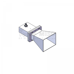
1. Horn antenna
The horn antenna is a planar antenna, a microwave antenna with a circular or rectangular cross-section that gradually opens at the end of the waveguide. It is the most widely used type of microwave antenna. Its radiation field is determined by the size of the horn's aperture and the propagation type. Among them, the influence of the horn wall on the radiation can be calculated using the principle of geometric diffraction. If the length of the horn remains unchanged, the aperture size and the quadratic phase difference will increase with the increase of the horn opening angle, but the gain will not change with the aperture size. If the frequency band of the horn needs to be expanded, it is necessary to reduce the reflection at the neck and the aperture of the horn; the reflection will decrease as the aperture size increases. The structure of the horn antenna is relatively simple, and the radiation pattern is also relatively simple and easy to control. It is generally used as a medium directional antenna. Parabolic reflector horn antennas with wide bandwidth, low side lobes and high efficiency are often used in microwave relay communications.
RM-DCPHA105145-20(10.5-14.5GHz)
RM-BDHA1850-20(18-50GHz)
RM-SGHA430-10(1.70-2.60GHz)
2. Microstrip antenna
The structure of microstrip antenna is generally composed of dielectric substrate, radiator and ground plane. The thickness of the dielectric substrate is much smaller than the wavelength. The metal thin layer at the bottom of the substrate is connected to the ground plane, and the metal thin layer with a specific shape is made on the front through photolithography process as a radiator. The shape of the radiator can be changed in many ways according to requirements.The rise of microwave integration technology and new manufacturing processes has promoted the development of microstrip antennas. Compared with traditional antennas, microstrip antennas are not only small in size, light in weight, low in profile, easy to conform, but also easy to integrate, low in cost, suitable for mass production, and also have the advantages of diversified electrical properties.
RM-MA424435-22(4.25-4.35GHz)
RM-MA25527-22(25.5-27GHz)
3. Waveguide slot antenna
The waveguide slot antenna is an antenna that uses the slots in the waveguide structure to achieve radiation. It usually consists of two parallel metal plates forming a waveguide with a narrow gap between the two plates. When electromagnetic waves pass through the waveguide gap, a resonance phenomenon will occur, thereby generating a strong electromagnetic field near the gap to achieve radiation. Due to its simple structure, waveguide slot antenna can achieve broadband and high-efficiency radiation, so it is widely used in radar, communications, wireless sensors and other fields in microwave and millimeter wave bands. Its advantages include high radiation efficiency, broadband characteristics and good anti-interference ability, so it is favored by engineers and researchers.
RM-PA7087-43(71-86GHz)
RM-PA1075145-32(10.75-14.5GHz)
RM-SWA910-22(9-10GHz)
Biconical Antenna is a broadband antenna with a biconical structure, which is characterized by wide frequency response and high radiation efficiency. The two conical parts of the biconical antenna are symmetrical to each other. Through this structure, effective radiation in a wide frequency band can be achieved. It is usually used in fields such as spectrum analysis, radiation measurement and EMC (electromagnetic compatibility) testing. It has good impedance matching and radiation characteristics and is suitable for application scenarios that need to cover multiple frequencies.
RM-BCA2428-4(24-28GHz)
RM-BCA218-4(2-18GHz)
Spiral antenna is a broadband antenna with a spiral structure, which is characterized by wide frequency response and high radiation efficiency. Spiral antenna achieves polarization diversity and wide-band radiation characteristics through the structure of spiral coils, and is suitable for radar, satellite communication and wireless communication systems.
Media Contact
Company Name: Chengdu RF Miso Co., Ltd.
Email: Send Email
Country: China
Website: https://www.rf-miso.com/
